Version 17 Available now. Contact us now to find out what's new.
Feature-rich
MBend
includes:
- Transferring parts directly from 3D CAD systems
- Importing and unfolding IGES and STEP 3D parts
- Importing and folding flat DXF\DWG parts with layer filtering
- Enabling automatic or manual selection of tools based on material, machine, and tool properties
- Calculating sequences automatically, avoiding collisions
- Allowing manual selection of sequences, in 3D, with collision testing
- Positioning fingers automatically, yet allowing manual snapping to adjust placement
- Calculating retractions automatically
- Simulating the bending process in 3D, displaying collisions
- Generating native NC programs for loading parts directly into machine controls
- Creating comprehensive setup reports for the machine operator including bend sequence, tooling, and bend-by-bend graphics
- A touch-screen version for machine controls
Advantages of MBend :
- Fully automated processing, including fully automated batch processing of multiple parts, enhancing your productivity and hastening design-to-production times
- Automatic collision-less sequencing solutions for an unlimited number of bends
- If a collision-less bend sequence exists, MBend will find it
- Solutions with a minimal number of stations and segments
- Unlimited number of fingers
FEATURES
MBend can import parts in 3D STEP/IGES or 2D DXF formats, export to 2D DXF, and exchange data directly with cncKad.
MBend allows
· Importing and unfolding 3D IGES and STEP parts
· Importing flat DXF and DWG files
· Transferring 3D parts from supported CAD applications using CAD Link
· Transferring parts directly to and from cncKad as a flat pattern
3D IGES/STEP Import
Use MBend to import parts in 3D IGES and STEP formats and unfold them. When you open the part, MBend analyzes the 3D geometry and unfolds it according to user-defined parameters such as a deduction table or DIN6935.
The part can then be tooled,
sequenced, and sent to the machine.
Flat DXF/DWG Import/Export
Import parts a flat DXF or DWG into MBend. When you open the file MBend displays a preview of the flat geometry with a layering filter. You can turn off any layers that do not hold the contour or the bend lines. MBend analyzes the information and turns it into a part that can be folded and unfolded. It can then be processed and sent to the machine.
When your part is ready for
production, you can export the flat pattern to a DXF file for further
processing.
CAD Link Transfer
CAD Link is an add-on to 3D CAD systems that links them to MBend.
3D models
are transferred directly between the systems, bypassing the need for
intermediate exchange files. The 3D application unfolds (flattens) the part
and CAD Link then transfers it to MBend. Once the export is complete, MBend opens, displaying the unfolded part.
CAD Link is available for the following CAD systems:
· Solid Edge®
· SOLIDWORKS®
· Autodesk Inventor®
· Catia®
· PTC Creo®
MBend tooling enables manual, automatic, and preferred tool selection, and saving or reuse of tool segment and position setups.
MBend tooling enables manual or automatic selection of tools, using your machine’s tools. You can save tool setups and use them for loading new parts.
MBend includes complete tool manufacturer catalogs. In addition, you can import tools and tool holders using DXF drawings or create tools parametrically.
MBend can unfold parts according to tool-specific compensation tables, ensuring precise cutting dimensions for blanks.
MBend supports tooling for all standard bend types:
· Normal bends
· Hemming bends
· Large radius bumping bends
MBend lets you designate preferred tools for one-click selection according to material and machine. This allows streamlined tool selection according to your preferences.
Automatic Tooling
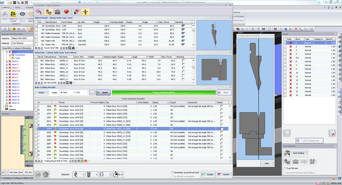
Automatic tool selection efficiently determines the best bending die/punch/holder tool combination based on these things:
· Tool geometry
· Desired bend radius
· Maximum allowable force
· Tool inventory and favorite tools
MBend can also look for a valid bend sequence for each tool combination, testing if it is useful for braking the part.
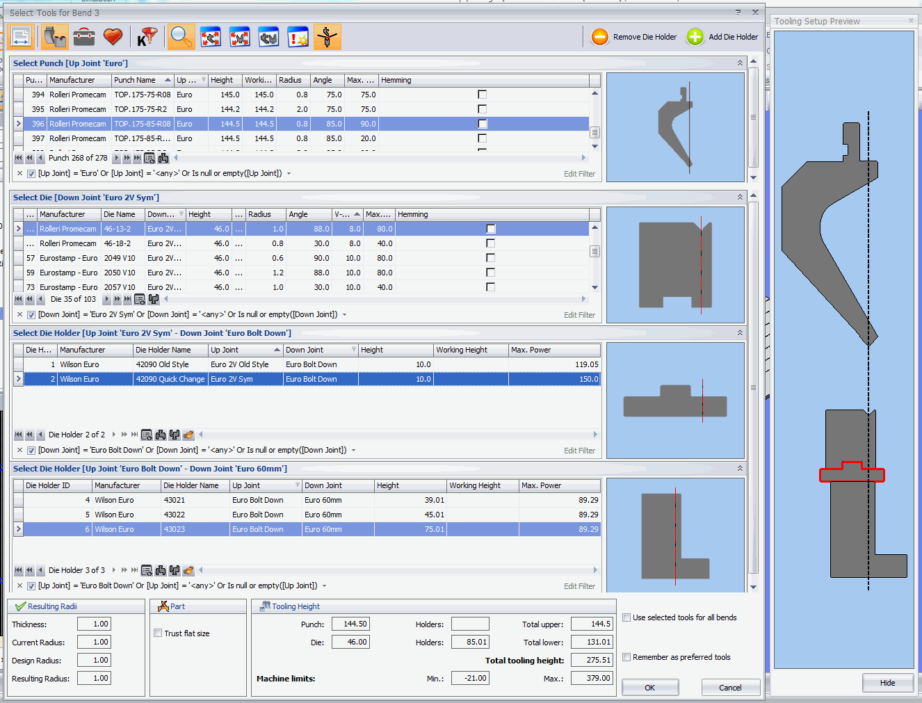
Manual Tooling
Manually select punch, die, and holder combinations from your company’s inventory.
During selection, the original design details are clearly displayed and MBend prevents you from choosing invalid tool combinations.
Stacking tools in MBend is easy. MBend guides your choices so you can only select stackable components.
Hemming
MBend ’s support for hemming includes
· Simulation of all common hemming tools: “Dutch”, spring-loaded, and flat
· Default hemming tools per machine for automatic selection
· Default and editable pre-bend angles
· Simulation of machines with hemming tables
Example of a spring-loaded hemming tool handled by MBend
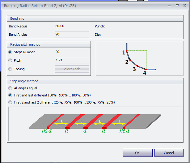
Bumping Bends
Large radius bumping is made by a series of shallow angled hits, designed to create a smooth result.
Flat Adjustment by Tooling
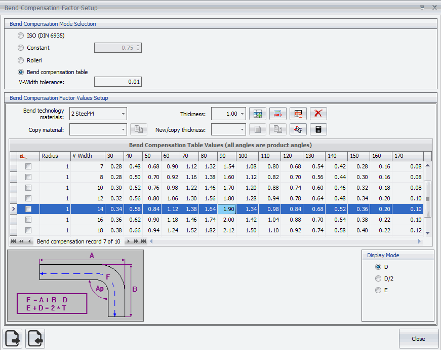
The
bend compensation table for steel, 1 mm: the values are in a grid according to
angle and tooling (V width)
MBend performs dynamic recalculation of flat size according to tool selection. You can select one of several optional calculation methods: bend compensation table, ISO, constant K, or Rolleri formula.
MBend can preserve the original flat pattern, regardless of the selected tools, while keeping the original folded product dimensions.
The video shows the impact of tooling on the flat pattern.
Tool Library
MBend includes complete, ready-to-use tool manufacturer catalogs. In addition, MBend supports easy creation and import of tools.
Tool Import from DXF
Easily import tools and tool holders from your DXF drawings. MBend automatically identifies all relevant dimensions (punch tip radius, height, v-width, etc.) and populates the database.
Define default settings per manufacturer to apply to all newly created tools for this manufacturer (segments/tool sectioning, heel dimensions, and tang height).
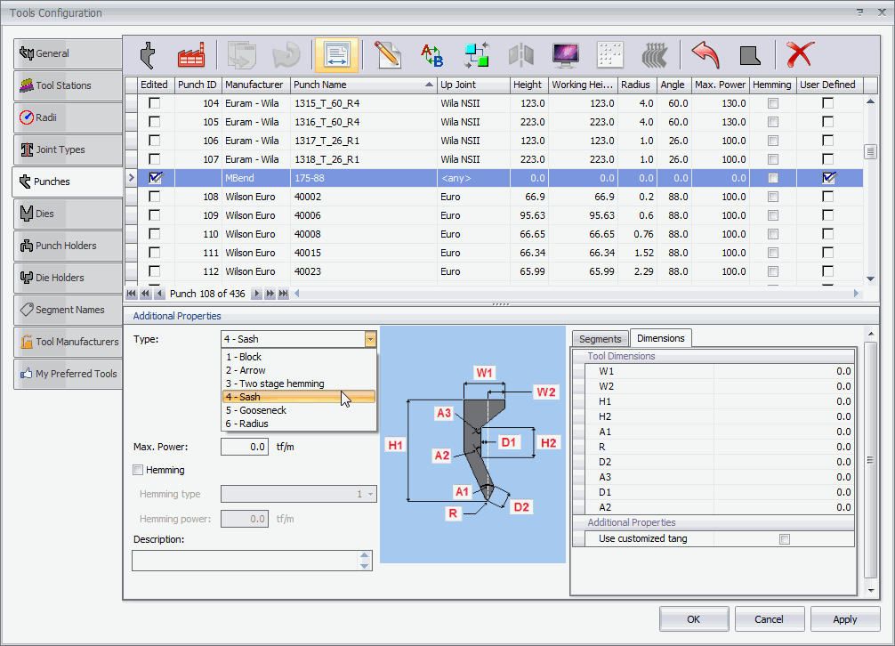
Parametric Tool Creation
Create punch and die tools by defining
their parameters. MBend supplies templates that resemble your
new shape, allowing you to adjust the dimensions to create a complete fit. In
addition to defining width, height, angle, and so on, define segments, heels,
maximum power, tang height, and up and down joints.
MBend enables manual selection or automatic calculation of bend sequencing.
MBend automatic sequence setting capabilities:
· Calculation of a collision-free sequence for any number of bends
· Optimized tool station setup calculation based on tool segment availability
· Intelligent tool segment distribution and clamping
· Heel tools for overhanging flanges
· Tool rotation (when possible) to avoid part rotations
· Hit splitting to avoid holder and table collisions
· Hemming bends
·
Divide
and merge tools for collinear (in-line) bends
Automatic Sequencing
After tool selection, MBend can automatically calculate bend sequences, based on different properties of the hits. You can choose the sequence that meets your requirements.
MBend calculates collision-free bending solutions that are ready for production, ensuring the machine operator does not waste time and material on trial runs.
If a collision-free bending sequence exists, MBend can find it.
Manual Sequencing
MBend
enables full manual control of
bending sequences:
· Set the bend sequence by folding the bends into the finished product
· Split bends into partial bends to avoid collisions
· Change sequences by dragging and dropping single and multiple bends into the order you want
· Use heels/horns
·
Rotate the part or the tools
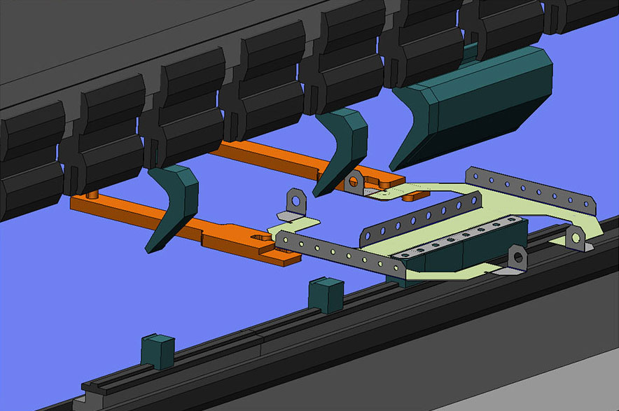
MBend provides options for automatic and full manual control of the finger positioning.
After you
set a bend sequence, either manually or with automatic sequencing, MBend automatically calculates finger
positioning.
MBend also calculates any retraction that is
required to avoid collisions between the fingers and up or down swinging
flanges.
To allow for user considerations, MBend also provides options for automatic and manual control over the backgauge:
· Snapping to a specific stop, e.g., from a front stop to a crab claw
· Searching for alternative stop positions
· Numerical and graphic control for all axes
Automatic Stop Positioning
MBend enables you to snap the fingers to any stop on the part, provided there are no resulting collisions. For example, when asked to snap to a support position, MBend checks if the flange is long enough and does not collide with the die.
MBend always searches for the optimal position to gauge the part, using all available stop positions. MBend tries gauging with flat and crab claw stops, depending on the finger and part geometries.
Crab Claw Snapping
One of MBend‘s finger snapping functions is automatic snapping to stops. It searches for the optimal position according to the finger stop type you select, whether flat or crab claw.
· For a crab claw stop, MBend clamps the part between the fingers.
· For a finger with more than one crab claw configuration, you can use different clamping.
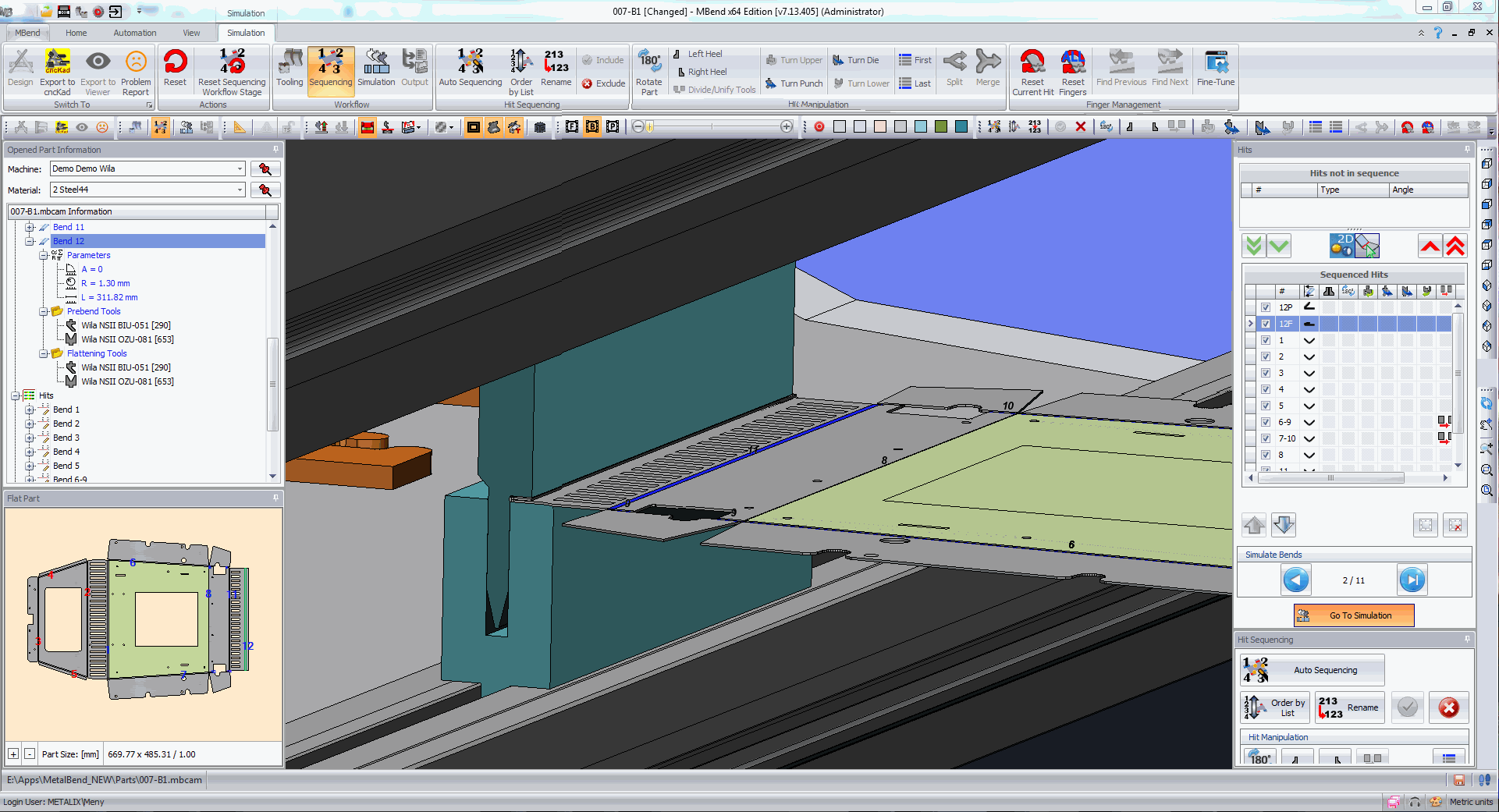
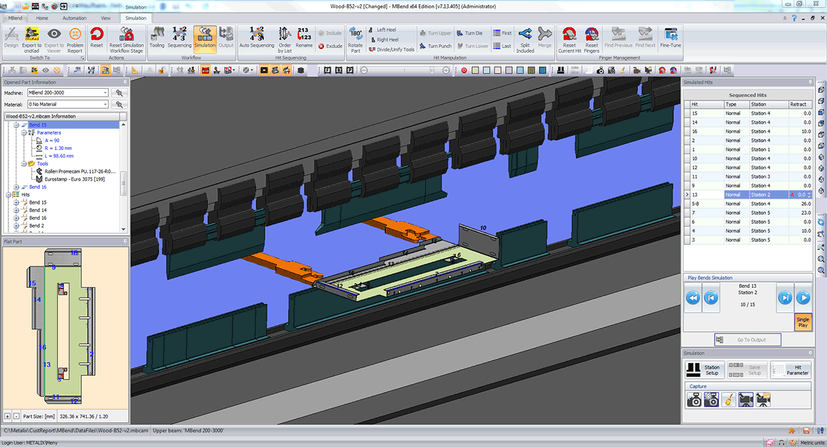
Simulating bends in MBend is a dynamic process, showing a realistic 3D visualization of the bending parts.
MBend provides a realistic visualization of the bending process in 3D, displaying any collisions that may occur during the process:
· With all moving elements
· Between the part and the machine, tools, and fingers
The realistic visualization includes overbend and springback.
Once MBend ensures the part will be collision-free, you
can generate NC code for the machine and reports.
Collision Testing for All Machine Parts
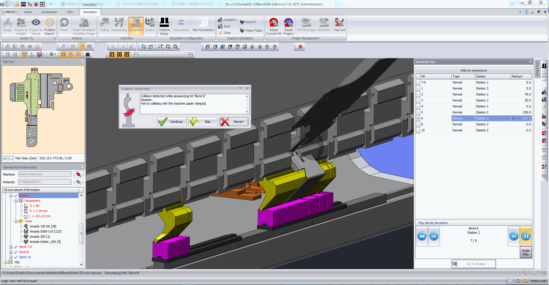
MBend simulates and performs collision detection for the part with all elements of the machine, i.e., fingers, tools, part, and machine frame. The simulation is done dynamically, displaying overbending and spring back, as well as finger movement between bends.
In addition, MBend can show the part handling – the movement of the part between bends. This is useful for viewing flips and rotations of the part and its movement between tool stations.
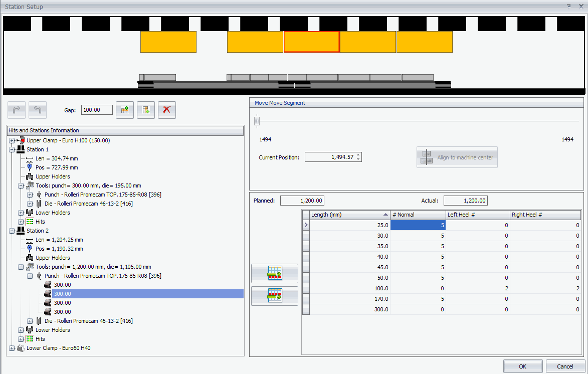
Tool Station Building
MBend automatically calculates the optimal tool stations for the part, taking into account:
· Available tool segments
· Secure spacing between stations to avoid collision during bending
· Secure clamping of segments
· Machine bending length
MBend
looks for a solution with the
minimal number of stations, and the minimal number of tool segments that allow
performing the bending sequence.
You can edit the tool stations manually, changing segments, adding or deleting stations and more.
Predefined Setups
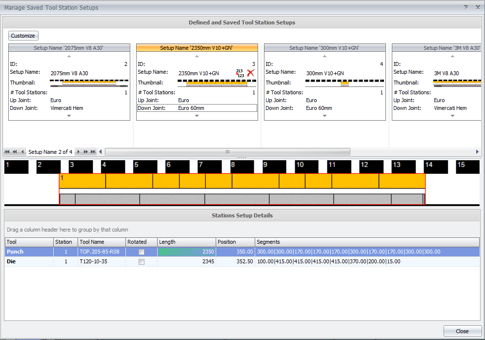
Another useful feature is saving the stations setup for reusing with other parts or in a batch script.
Video Capture
In MBend, you can grab images or record a video of the simulated hits and save them to file.
It is possible to create a separate video for every hit. You can also determine the maximum file size to create, so that your hard disk does not run out of available space.
MBend creates NC code suitable for most machines and controllers.
MBend can generate native NC files for most machines and controllers, including these:
· Cincinnati
· CoastOne
· Cybelec
· Delem
· Durma
· ESA
· Komatsu
· Muratec
· Toyokoki
·
Trumpf
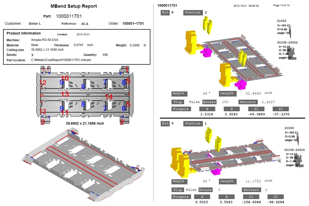
Comprehensive MBend reports include all the information the operator needs to set up the tooling and bend the part.
Comprehensive MBend reports include all the information the operator needs to set up the tooling and bend the part.
Information includes:
· Tool information and tool setup details
· Bend sequence instructions
· Flat view with the bend sequence
· Product handling
· Bend-by-bend graphics
MBend provides several pre-formatted report templates:
· General-purpose system reports, provided by Metalix, corresponding to the language(s) you select. Edit them with a CR editor.
· Built-in reports.
You can
generate your report files in several formats: PDF, DOC, RTF, XLS\XLSX, XML,
CSV, and RPT.
The MBend automation feature allows batch processing your parts.
MBend can process parts in batches, using selections of native MBCAM, 3D (IGS, STEP) or 2D (DXF, DWG) parts to generate machine-ready NC files and setup reports.
You can determine how to process a group of parts and save the settings for later use as a script file.
Select individual parts or entire folders to process, choose a machine—optionally deciding to generate NC and reports—and configure backup processes to run if the first configuration fails.
MBend starts batch processing, running each part through automatic tooling, sequencing, simulation, and output generation using the configuration settings.
If processing a particular file fails (maybe because no appropriate tools are found, or because no sequence is collision-free), MBend proceeds to process the next part, and so on. When one part is processed successfully, output is generated. MBend then tries to process the failed parts using the next defined configuration.
You can
manually change the predefined batch processing options.
With the MBend module of designing parts you can draw part profiles.
Use the MBend design module to sketch a part profile, refine its flange dimensions and angles, and save it in the profile library for later reuse.
MBend also includes a basic 3D CAD designer.
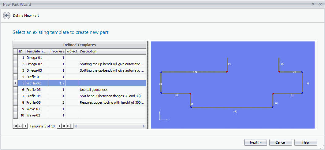
Profile Designer
Draw the profile design freehand, and then adjust the draft measurements so they are exactly what you need.
You can save the profile with a name in the library of profile templates, and then use it as your base whenever you need to create a part with a similar basic design.
When you want to use a profile from the template library, MBend shows you a preview of each saved template.
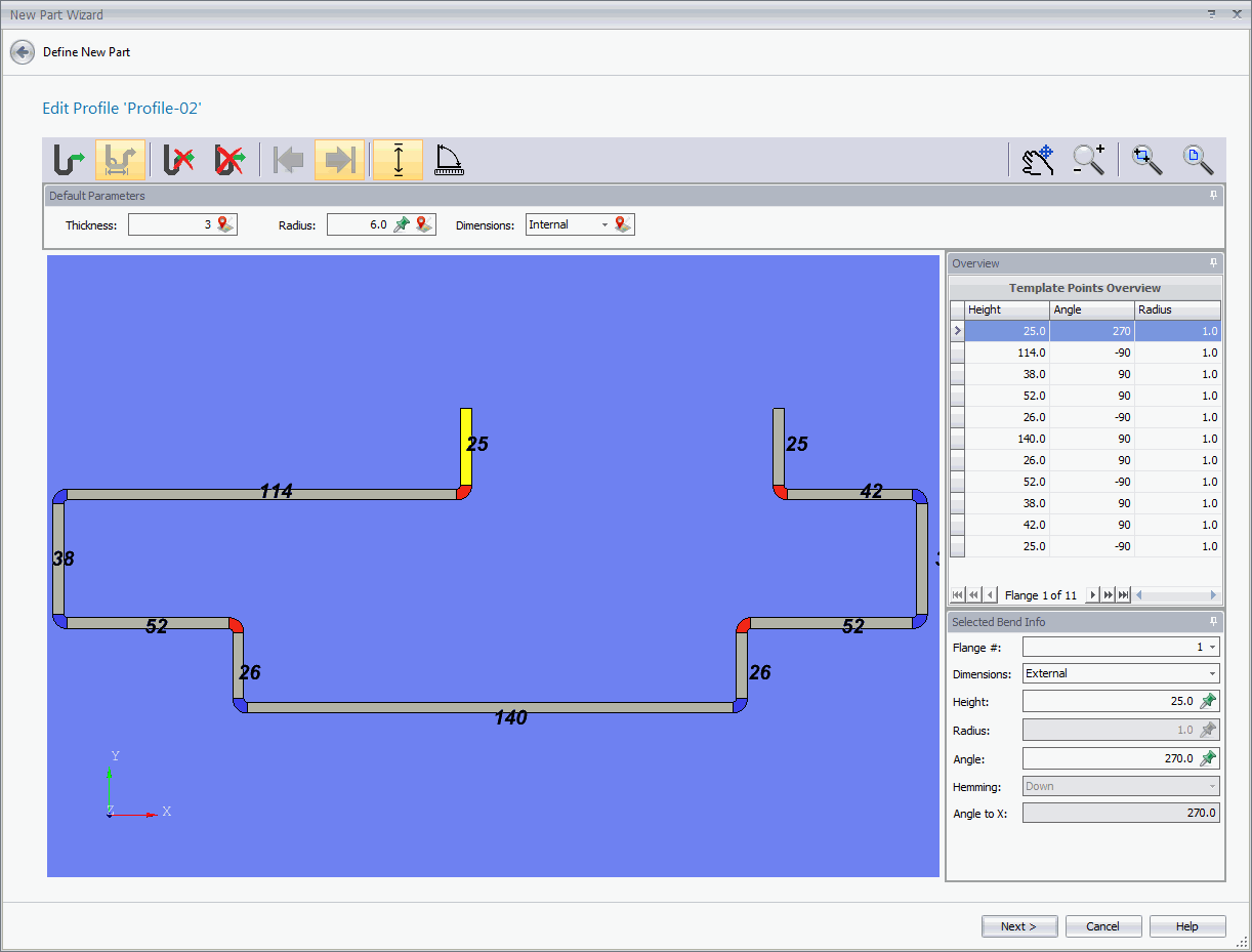
You can edit the profile, changing its dimensions.
You can open it in the design module for adding 3D elements or open the part directly in the Simulation mode.
3D CAD Designer
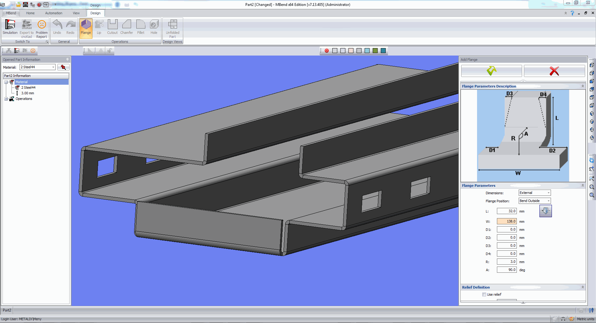
MBend includes a basic 3D CAD designer for creating sheet metal parts. Open an existing part or create a part based on a profile, and then add flanges, lips, cutouts, chamfers, fillets, and holes.
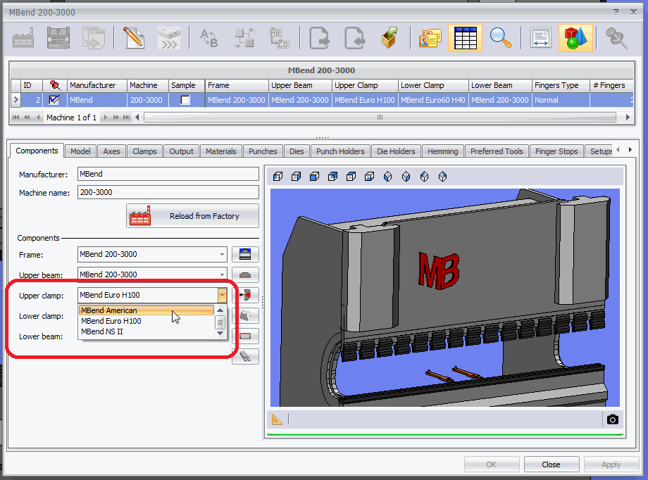
Machine Configuration allows to import and configure tools and machines.
MBend provides roughly 200 pre-configured machine models out of the box. If your specific model is not in the list, you can easily modify an existing machine to match yours.
You can also add a machine in MBend to those already available for simulation. A built-in wizard guides you in the process of configuring a new machine, including assigning the tools, whether from imported definitions, existing definitions in MBend, or manual configuration.
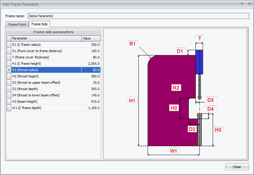
There are three ways to add a new set of definitions:
· Define all the parametric measurements.
· Import an IGES file.
· Import machine and tool parameters from another PC running MBend.
Defining
a parametric frame is just a matter of measuring the machine and entering the
relevant information in the template.